IPT lança manual para situações emergenciais que contempla todas as etapas, da captação à utilização da água de chuva
A captação da água de chuva hoje é realidade para muitos moradores de cidades como São Paulo, que vêm enfrentando uma crise hídrica que já afeta o abastecimento de diversos domicílios. Levando em conta este cenário, o IPT lança agora um manual que busca oferecer à população orientações para melhorar a qualidade dessa água, apresentando as boas práticas para a sua captação, armazenamento e utilização doméstica.
O manual, lançado em comemoração ao Dia Mundial da Água, 22 de março, é direcionado a famílias que vivem situações emergenciais e dissemina uma técnica relativamente simples, mas que respeita os requisitos que garantem o funcionamento do sistema e, principalmente, assegura a qualidade da água coletada.
De acordo com o pesquisador e autor do manual Luciano Zanella, do Centro Tecnológico do Ambiente Construído do IPT, o projeto nasceu da constatação de que não apenas a captação da água de chuva, mas também seu tratamento e armazenagem, muitas vezes são feitos de maneira equivocada. “Embora a melhor água seja aquela oferecida pela concessionária, não podemos fechar os olhos ao fato de que muitas famílias hoje convivem com abastecimento irregular e têm se valido dessa solução. É preciso, no entanto, oferecer condições para que a captação seja feita de maneira mais segura, lacuna que o IPT pretende preencher com este manual”.

Ilustração do sistema de captação da água da chuva
O trabalho do IPT mostra como requisitos fundamentais a captação da água pelo telhado, e não pelo piso, além da filtragem que será responsável pela primeira limpeza, separando o líquido dos objetos sólidos como as folhas das árvores que acabam entrando no captador. Outro passo essencial no processo, geralmente desconhecido, é o descarte da água da primeira chuva, que carrega a poluição atmosférica e os contaminantes presentes no telhado. O recomendado é que sejam descartados dois litros de água para cada metro quadrado de área do telhado utilizado na captação, o que corresponde aos dois primeiros milímetros de precipitação.
O sistema proposto no manual é de fácil instalação. Foi pensado para situações emergenciais e não está integrado ao sistema hidráulico predial. “Os usuários podem fazer adaptações ao material, desde que sigam os parâmetros fundamentais. Essa água poderá ser usada para descarga de bacias sanitárias, limpeza de pisos e veículos e rega de jardins e áreas verdes”, explica Zanella. Numa situação extrema, caso falte água de qualidade superior, a água de chuva – desde que captada, tratada e armazenada adequadamente – também pode ser utilizada para ingestão e preparo de alimentos. Para esse uso, além das etapas anteriores, recomenda-se ainda a fervura por um tempo superior a três minutos, melhorando a segurança sanitária.
O manual é gratuito e pode ser acessado clicando aqui
fonte: IPT
This white paper explores how the reliable information held within a building information model can be used to support cost estimating. The paper outlines approaches used to link BIM and costing solutions, and then provides examples of firms who are using Revit® software products in conjunction with various cost estimating solutions, offering insight as to how information from BIM is benefiting architects, quantity surveyors and cost estimators, and builders – as well as their clients.
Model-based Estimating A purpose-built BIM solution like Revit features computable building information that enables a model to be understood by a computer as a building. A wall for example, “knows” what it is and how to react to the rest of the building. As such, it can be scheduled or quantified as a wall: a building assembly made of real materials. Computable building information supports numerous building design and construction activities: structural analysis, MEP system modeling, building energy analysis, and specification management, to name just a few. Cost estimating is yet another aspect of the building process that can benefit from computable building information. Designing a building is the responsibility of architects, whereas assessing the cost to build it is the domain of estimators. In general, the architect’s scope of work doesn’t extend to material takeoffs or cost information. That’s left to the estimator. When preparing their cost estimates, estimators typically begin by digitizing the architect’s paper drawings, or importing their CAD drawings into a cost estimating package, or doing manual takeoffs from their drawings. All of these methods introduce the potential for human error and propagate any inaccuracies there may be in the original drawings. By using a building information model instead of drawings, the takeoffs, counts, and measurements can be generated directly from the underlying model. Therefore the information is always consistent with the design. And when a change is made in the design – a smaller window size, for example – the change automatically ripples to all related construction documentation and schedules, as well as all the takeoffs, counts, and measurements that are used by the estimator. The time spent by the estimator on quantification varies by project, but perhaps 50-80% of the time needed to create a cost estimate is spent just on quantification. Given those numbers, one can instantly appreciate the huge advantage of using a building information model for cost estimating. When you do not require manual takeoffs, you can save time, cost, and reduce the potential for human error. In fact, a common complaint from estimating firms is how much they hate paying estimators to simply count or quantify when they bring so much more expertise and experience to the table. By automating the tedious task of quantifying, BIM allows estimators to use that time instead to focus on higher value project-specific factors – identifying construction assemblies, generating pricing, factoring risks, and so forth – that are essential for highquality estimates. For example, consider a commercial project slated for construction in northern Minnesota in the winter. The estimator will realize that winter heating and dewatering will be needed for a portion of the concrete substructure. This is the sort of specialized knowledge only professional estimators can factor in to the cost estimate accurately. This construction wisdom, not “counting,” is the real value professional estimators bring to the cost estimating process.
Many Paths from BIM to Costing There are a variety of ways of getting quantities and material definitions out of a building information model into a cost estimating system. Broad categories of integration approaches include: • Application Programming Interface (API) to commercially available estimating programs from vendors such as U.S. COST or Innovaya (which then integrates with Sage Timberline Office Estimating). This approach uses a direct link between the costing system and Revit. From within Revit, a user exports the building model using the costing program’s data format and sends it to the estimator, who then opens it with the costing solution to begin the costing process. • ODBC connection to estimating programs such as CostX or ITALSOFT – popular Australian and Italian cost estimating solutions, respectively. ODBC is a tried and true standard, useful for integrating data-centric applications like specification management and cost estimating with building information modeling. This approach typically uses the ODBC database to access the attribute information in the building model, and then uses exported 2D or 3D CAD files to access the dimensional data. Part of the integration includes a reconstitution of the building data within the costing solution – linking cost geometry, attributes, and pricing. • Output to Excel. In comparison to the approaches outlined above, quantity takeoffs done within Revit and output to a Microsoft® Excel® program may seem lackluster, but the simplicity and control is perfectly suited to some costing workflows. For instance, many firms just create material takeoffs in RRevit, output the data to a spreadsheet, and then hand it off to the cost estimator.
There are no right or wrong approaches – each integration strategy is based on the estimating workflow used by a specific firm, the costing solutions they have in place, the pricing databases they use, and so on. To illustrate these approaches, four customer examples are presented below, each one detailing a different BIM-to-costing workflows: an API integration between Revit and Innovaya’s estimating solution; another API integration between Revit and U.S. COST; a BIM to costing solution link using ODBC; and outputting data from Revit directly to spreadsheets, which are then used as input for costing. Better Numbers Ryan Companies (www.ryancompanies.com) is a leading national commercial real estate firm offering integrated design-build and development as well as asset, property and facilities management services to its customers. With offices throughout the United States, Ryan uses the power of BIM to accurately coordinate building information within the documentation set, and provide their estimators and construction team with solid, up-todate building information. As a design/build firm, Ryan was an excellent candidate for adopting a model-based approach to estimating; design and costing are done under one organizational roof, which minimizes scope of work issues relating to takeoffs. Established Revit users, they have just started to use Innovaya’s Visual BIM and Quantification products, which enables estimators to visualize the Revit building model in a costing-oriented 3D environment (for example, get a 3D view of structural slabs with concrete columns and shear walls), perform quantification, and add construction assembly data. For pricing information, Visual Estimating can be linked to Timberline or information can be output to Excel for use with other pricing solutions, as is the case with Ryan Companies.
Dick Bates, Ryan’s CAD Manager, uses this example to explain the difficulties associated with quantification from a design model. “For any given wall, we need to calculate three numbers to get a price: the gross area of one side of the wall to get material quantities totaled for each wall type, and then the double gross and net areas to quantify finishes.” The programmatic link between the two solutions means that Innovaya’s solution can count and calculate materials directly from the Revit building information model. The quantity extraction methods are easily customized (for instance, calculating the three wall areas cited in the example above from a single design element) and are reusable for multiple projects. Quantities are extracted based on building element types and their dimensions. Once the quantification is complete, Ryan’s estimator outputs the data from Innovaya to an Excel spreadsheet for entry into their in-house pricing program. And with the API link, the quantities are automatically associated with the Revit building, so they “remember” where they came from. This means that the Innovaya software can easily detect design changes from the Revit model, which allows the estimator to validate previous quantities against the new design, and then automatically update those quantities. As Bates explains, “In the past, our estimators had to manually check design revisions for cost implications. Now we just re-export the Revit model to Innovaya, and let the costing software figure out what has changed.” According to Bates, “We’re very excited about the integration between Revit and Innovaya. All the data we need for high-quality costing is in the Revit model. With this integration, our estimators are getting better numbers from the building model, and we can continue to use each program for its intended purpose: Revit for building design and Innovaya for construction estimating.” Linking Design Decisions to Costs via an API Oculus Inc. (www.oculusinc.com) is a 30-person architectural, strategic facility planning, interior design, and move management firm with offices in St. Louis, Dallas, and Chicago. Since their 1994 inception they’ve been committed to meeting voids in the offerings of traditional firms; helping their clients maximize the value of their investments by linking architecture to master planning, long range forecasting, space planning, and interior design. Integral to that commitment is the concept of architectural design linked to cost: informing their design decision making process. A longtime Revit user, Oculus immediately recognized BIM’s potential for data-intensive applications such as facilities management and costing. According to Ron Reim, Oculus principal and co-founder, “BIM enables us to get better information about our projects, so we can give better advice to our clients.” They recently started to use Revit in conjunction with estimating software from U.S. COST (www.uscost.com), an Atlanta-based company that provides cost management and project control services and software. Oculus was already quite familiar with U.S. COST’s estimating software, Success Estimator, as many of their outsourced cost estimates are developed with it and Oculus routinely (but painstakingly) checks those estimates against their design model – verifying the estimate for their client. So they were closely tracking the API integration between Revit and Success Estimator (the commercial product is called Success Design Exchange), looking forward to replacing those manual checks with programmatic ones. Once the API link was complete they sent an architect, with a background in specifications and costing, to a U.S. COST training class and they’ve recently begun using Success Estimator and Design Exchange themselves.
They will still work closely with cost estimators on large projects, but by using Success Estimator internally Oculus can quickly develop cost baselines for their Revit projects and deliver optimal designs that honor their clients’ budgets. They can also produce quick cost estimates on small, fast-track projects; dramatically reducing the delays associated with outsourcing, and using the time and cost savings strategically – in the form of lower fees and/or more front-end design time, as they see fit. In addition, they expect to capitalize on their new in-house costing capability for expanded design/build partnerships and projects. “The ability to get dead-on counts from the Revit model has meant a huge improvement for timely, accurate costing,” states Reim. “Now with the link between Revit and U.S. COST, we can use those quantities ourselves to develop our own cost estimates or streamline the verification of outsourced cost estimates.” Scope Management using ODBC Turner & Townsend Rawlinsons (www.turnerandtownsend.com.au), one of Australia’s largest construction and management consultancies, has a hands-on, can-do approach to new technology and are committed to improving their product through IT. One example of this commitment is their innovative use of IT solutions throughout the costing process, including the use of Exactal’s (www.exactal.com) flagship product CostX – a popular Australian cost estimating package. To accurately estimate cost and variations as they occur, CostX features bi-directional ties into design solutions, including a recently released ODBC-based integration between CostX and Revit that Turner & Townsend Rawlinsons has been quick to capitalize on. Usually Turner & Townsend Rawlinsons are sent 2D electronic CAD files from their clients, which they import into CostX – propagating any inaccuracies there may be in the original drawings. But their clients using Revit can now provide Revit views in the DWG™ file specification and the Revit model exported to an ODBC database. The combination of dimensional data from the DWG files and attribute information in the ODBC database is automatically detected and reconstituted by Exactal’s Revit integration, enabling high quality quantity surveys and helping to stem client dissatisfaction with “scope creep.”
According to Dave Liddle, quantity surveyor and principal of Turner & Townsend Rawlinsons, “Scope management requires tools to analyze change over time. We’re constantly updating cost estimates during the design process – comparing and evaluating pricing changes due to design changes.” The Revit-to-CostX integration ties costs directly to dimensions: Cost Geometry® business management software, to use Exactal’s terminology. “We don’t have to manually compare drawings and re-takeoff materials. The link between Revit and CostX automatically detects the changes and graphically displays the results, which allows us to easily see the areas that have changed and quickly re-cost the model,” states Liddle. “The time savings allows us to do a better job estimating and reduces scope creep – to the delight of our clients.” [Note: In July 2006, Exactal released a second Revit integration based on Autodesk’s DWF™ technology, built to distribute CAD files and 3D models so intelligence of designs can be communicated even more easily and securely.
Accurate Quantification with Revit and Excel Founded in 1885, Parsons Brinckerhoff or PB (www.pbworld.com) is one of the oldest continually operating consulting engineering firms in the United States. PB’s St. Louis office offers professional services in architecture; civil, structural, mechanical, electrical, plumbing, fire protection, environmental, and geotechnical engineering; landscape architecture; planning; and program/construction management. With a staff of more than 70, PB’s St. Louis office provides services throughout the United States and are supported by the specialized expertise of PB’s national service groups who are available as needed to assist the local staff. PB’s St. Louis office was an early adopter of BIM and have been using Revit for all facets of building design for more than five years. They’re committed to achieving their client’s cost objectives and vigilantly heed the cost estimating adage: the one who gets the low bid is the one who left something out. Thus, they rely on getting accurate quantities for accurate cost estimates: extracting quantities from the Revit building information model, outputting them to a text file, importing that to Excel, and then sending the spreadsheet to their estimators for costing. They typically produce at least two cost estimates: at the end of schematic design and a complete estimate at the end of detailed design. The first estimate used to be quite general, usually based on standard ‘rule of thumb’ square footage costs. “By using the quantities from Revit, we get detailed estimates much earlier in the process,” reports Tom Brooks-Pilling, Director of Architecture for the PB St. Louis office. “For example, the initial estimate may have included only allowances for finishes, but with the level of detail in Revit we can often replace allowances for actual quantities – even during schematic design.” “We pride ourselves on preparing realistic solutions that fit our clients’ needs as well as their budget,” explains Brooks-Pilling. “The quantification capabilities of Revit allow us to generate cost forecasts for decision-support, making it easier for us to meet our clients’ design and cost expectations.”
Summary The first step of cost estimating is quantification – and the computable information at the heart of a building information model makes quantification effortless. BIM solutions don’t generate automatic cost estimates by any means, but they offer significant advantages over traditional drawing-based systems by minimizing manual takeoffs. More accurate quantities of materials results in more accurate cost estimates. Reducing the quantification effort means estimators can more effectively apply their time and knowledge to higher value estimating activities. And architects can use the information within their design model to easily double check estimating quantities – facilitating concurrent estimating during the design process. About Revit The Revit platform is Autodesk’s purpose-built solution for building information modeling. Applications such as Revit® Architecture, Revit® Structure, and Revit® MEP built on the Revit platform are complete, discipline-specific building design and documentation systems supporting all phases of design and construction documentation. From conceptual studies through the most detailed construction drawings and schedules, applications built on Revit help provide immediate competitive advantage, better coordination and quality, and can contribute to higher profitability for architects and the rest of the building team. At the heart of the Revit platform is the Revit parametric change engine, which automatically coordinates changes made anywhere — in model views or drawing sheets, schedules, sections, plans… you name it. For more information about building information modeling please visit us at http://www.autodesk.com/bim. For more information about Revit and the discipline-specific applications built on Revit please visit us at http://www.autodesk.com/revit.
A construção da nova ponte sobre o rio Colorado, junto à barragem Hoover, teve como principal objectivo ultrapassar os problemas de congestionamento de tráfego, provocados pelas restrições de circulação sobre a barragem. Esta ponte, que abriu ao tráfego no final de 2010, é a peça central de um enorme projecto de construção denominado Complexo de Bypass da Barragem Hoover.
A construção iniciou-se em Janeiro de 2005, de forma algo atribulada, devido problemas de financiamento, que foram prontamente ultrapassados devido à importância fundamental do projecto, que permitiria ligar de forma eficiente, por auto-estrada, o estados do Arizona e Nevada. Em 2006 a obra sofreu novo percalço, quando as torres onde estavam amarrados os cabos de suporte da grua suspensa, colapsaram sob acção de ventos intensos.
O tabuleiro tem cerca de 600 m de comprimento e foi construído sobre um arco duplo de betão armado em pré-esforço, com 320 m de vão. Esta estrutura massiva, que exigiu 7300 toneladas de aço de reforço, 600 km de cabo de aço e 23 mil metros cúbicos de betão, situa-se a 270 m acima do Rio Colorado, sendo a sétima ponte mais alta do mundo. Os pilares extremantes têm cerca de 90 metros de altura.

O projecto e construção custaram 240 milhões de dólares, envolvendo, de forma permanentemente ao longo de 5 anos, 1200 operários e 300 engenheiros.
A integração harmoniosa com uma das mais marcantes obras de Engenharia Civil de todos os tempos, a Barragem Hoover, granjeou-lhe reconhecimento internacional, atraindo milhares de turistas, desde a sua recente inauguração.
fonte: Engenharia Civil.com
O Brasil encontra-se neste momento na maior fase de crescimento económico e humano da sua história. O mais importante motor desse desenvolvimento é a indústria da construção. Grandes obras de Engenharia Civil estão planeadas para os próximos anos no Brasil, algumas das quais de grande dimensão e complexidade.
Ao longo de uma série de artigos iremos apresentar algumas das mais importantes obras de engenharia civil que se vão realizar no Brasil. No entanto é também importante conhecer as realizações passadas da engenharia civil brasileira, conhecida em todo mundo pela sua proficiência técnica e capacidade de optimização e por ter sido responsável por algumas das mais importantes obras de Engenharia Civil da América do Sul. Apresentam-se a seguir três exemplos da excelência técnica da engenharia civil no Brasil.
A Maior Barragem do Brasil – Complexo Hidroeléctrico de Itaipu
O Complexo Hidroeléctrico de Itaipu está localizado no Rio Paraná. A sua construção foi resultado de uma parceria entre o Brasil e o Paraguai e continua a ser uma das maiores barragens do mundo. Tem uma potência geradora de cerca de 14 mil MW, 20 unidades de geração de energia eléctrica e fornece uma parte muito significativa da energia eléctrica consumida em ambos os países. A sua construção implicou o uso de 13 milhões de m3 de betão e a intervenção de cerca de 40 mil operários.
mais em
fonte: Engenharia Civil.com
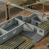
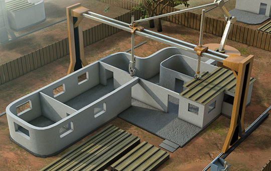
O Contour Crafting é um processo construtivo que utiliza um dispositivo semelhante a uma impressora 3D de grandes dimensões para a execução de estruturas de Engenharia Civil. Criado pelo Professor Behrokh Khoshnevis da Universidade da Califórnia do Sul, permite a automação parcial da construção de paredes, lajes, vigas, pilares e outro tipo de elementos de edifícios.
A tecnologia baseia-se no fabrico por camadas, no qual um mecanismo extrusor de injeção, movido por um sistema de posicionamento robótico controlado por computador, aplica a argamassa em sucessão, de acordo com a geometria do projeto tridimensional a executar.
A cadência de aplicação do material aplicado, seja betão de cimento ou adobe por exemplo, tem em conta o tempo de secagem e cura bem como outras propriedades, como a trabalhabilidade ou o índice de vazios.
Graças à possibilidade de existência de múltiplos reservatórios e condutas de injeção, o sistema permite a alternância entre materiais, sem necessidade de paragem do processo para troca ou lavagem do injetor.
Apesar de existirem outros sistemas baseados nos mesmos princípios, o Contour Crafting tem a vantagem de permitir um acabamento mais refinado dos elementos construtivos, graças à incorporação de espátulas de aço que funcionam como colheres de pedreiro.
O sistema faz a colocação automática de armadura de aço, utilizando componentes metálicos modulares, possibilitando a execução de elementos de betão armado muito semelhantes aos convencionais.
É possível também o reforço com fibras de aço ou a utilização de polímeros reforçados com fibras (FRP).
Outras potencialidades do processo incluem a colocação automática de elementos de pavimentos e azulejos, bem como a instalação das condutas de redes de águas, energia e comunicações. O Contour Crafting permite até a pintura automática final da estrutura, como se de uma linha de montagem se tratasse.
fonte: Engenharia Civil.com
Após quatro longos anos de construção, a Ponte Flutuante Evergreen Point, em Seattle, EUA, foi finalmente inaugurada esta semana, devendo abrir parcialmente ao tráfego na próxima segunda feira. Conhecida como “SR 520”, a obra de arte rodoviária, cicloviária e pedonal, é a mais longa ponte flutuante do mundo, com 2350 metros de comprimento. A opção pela execução de uma estrutura flutuante resultou das características singulares do Lago Washington, que chega a ter 65 m de profundidade em alguns pontos.
fonte: Engenharia Civil.com
Projeto do arquiteto francês Christian de Portzamparc também empregou vidros curvos coloridos, especificados após exaustivos testes em fábrica.
Primeiros 60 pavimentos do edifício One 57 foram ocupados pelo hotel Park Hyatt New York, e os 15 restantes por apartamentos de dimensões variadas, com vistas para o Central Park.

RESUMO
Torre One 57
Localização: Nova York
Área construída: 74.353 m²
Cliente: Extell Development Corporation
Construção: WSP Cantor Seinuk, AKF Engineers
Arquitetura: Atelier Christian de Portzamparc
Interiores: Thomas Juul-Hansen (apartamentos) e Yabu Pushelberg (hotel)
Consultoria de fachada: Israel Berger Associates
Iluminação: Tillotson Design Associates
Tipologia: Uma torre de 75 pavimentos e dois subsolos, para hotel (60 pavimentos) e apartamentos residenciais (15 pavimentos)
Estrutura: Núcleo central de concreto armado pilares e vigas de concreto pré-moldado
Fachada: 8.200 módulos unitizados com 2.200 configurações diferentes cobrindo uma área de 47,3 mil m²
Inicio da obra: 2009
Conclusão da obra: novembro de 2014
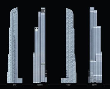
Nova torre apresenta faces envidraçadas e assimétricas que se reduzem e se transformam à medida que se elevam, apresentando desenhos diferentes para cada um dos pontos cardeais.
Uma equipa conjunta do Instituto Fraunhofer de Maquinação e Tecnologias Metalúrgicas (IWU), sediada em Dresden e do Departamento de Design de Têxteis e Superfícies da Escola de Arte Weissensee, em Berlim, está a desenvolver componentes de fachada inteligentes com a capacidade de se adaptarem, de forma autónoma, à intensidade dos raios de sol. A tecnologia faz uso de elementos com memória de forma, que requerem apenas a energia térmica do sol para funcionarem.
O sistema, criado através do trabalho conjunto de engenheiros e designers pretende reduzir os enormes consumos energéticos decorrentes do funcionamento dos ares-condicionados para o controlo da temperatura, em edifícios com fachadas envidraçadas.
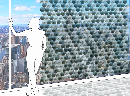
O protótipo desenvolvido pelos investigadores é constituído por uma matriz de 72 elementos de tecido em forma de flor. Cada um destes elementos possui no seu interior um conjunto de atuadores fabricados com uma liga metálica de níquel-titânio com memória de forma. Estes materiais têm a capacidade de voltar à sua forma original quando expostos a uma fonte de calor.
Os elementos de tecido podem ser colocados no extradorso dos painéis envidraçados ou protegidos entre camadas de vidro.
Quando a fachada aumenta de temperatura por ação do sol, os atuadores são ativados e assumem a sua posição original, fazendo com que os elementos de tecido se abram e impeçam que os raios solares penetrem no interior dos compartimentos.
Assim que os raios solares deixam de incidir na fachada e a temperatura desta desce, os atuadores fazem com que as “flores” de tecido voltem a fechar.
A tecnologia, que foi dimensionada para poder ser utilizada nas grandes superfícies envidraçadas, planas ou curvas, dos modernos arranha-céus, pode ser facilmente aplicada a edifícios existentes, uma vez que não exige que os painéis envidraçados sejam retirados ou substituídos.
Além disso, os elementos podem ter diferentes geometrias além da forma em flor, como em favo de mel ou em triângulo, o que possibilita uma mais fácil integração estética no edifício.
fonte: EngenhariaCivil.com